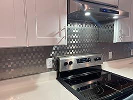


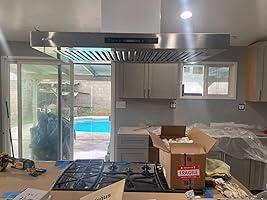


We have a new IKTCH 4o inch hood and it looks great and works well. We were missing a part and the customer service team was responsive and courteous and creative in finding ways to solve our issue.
Thank you for your support and the positive feedback on our IKTCH 42-inch range hood! We're thrilled to hear that you're satisfied with both the product and our customer service team.
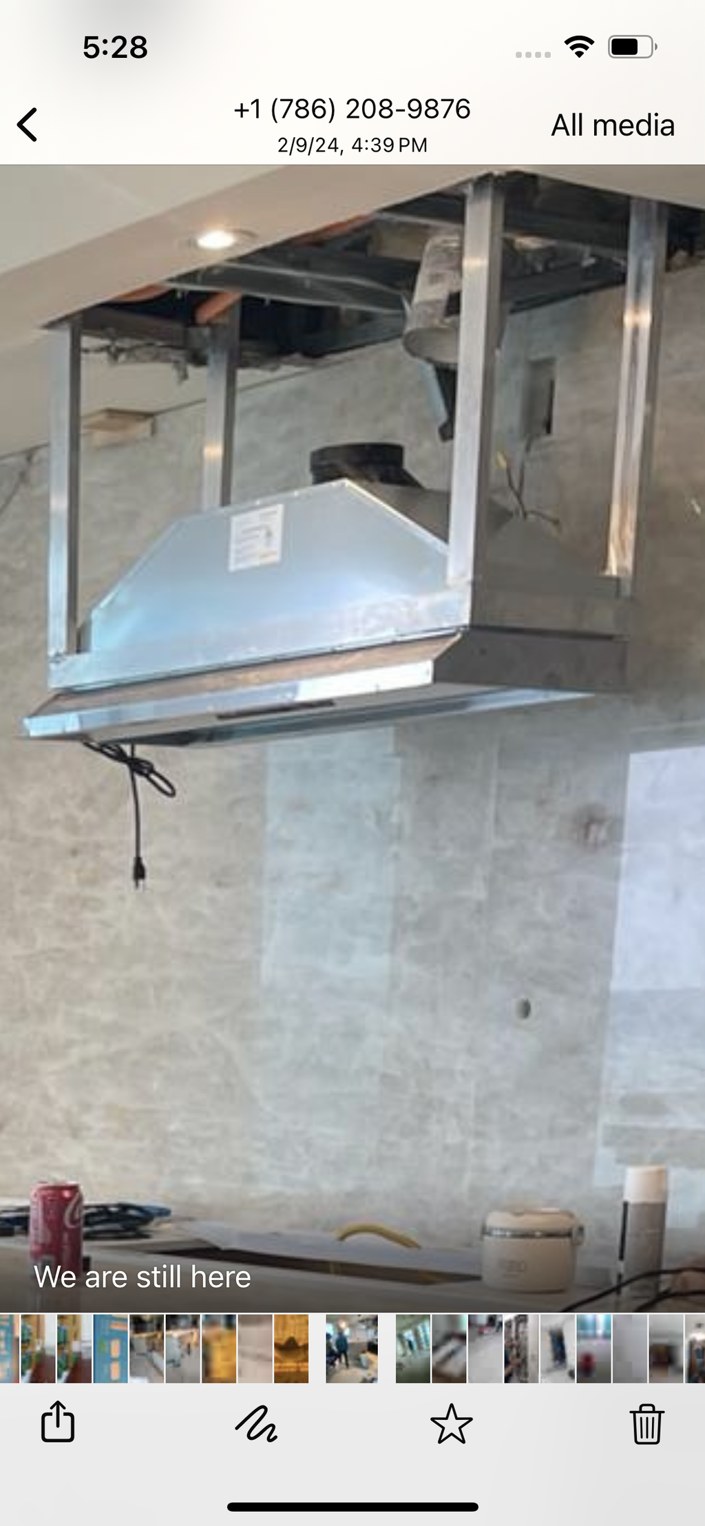
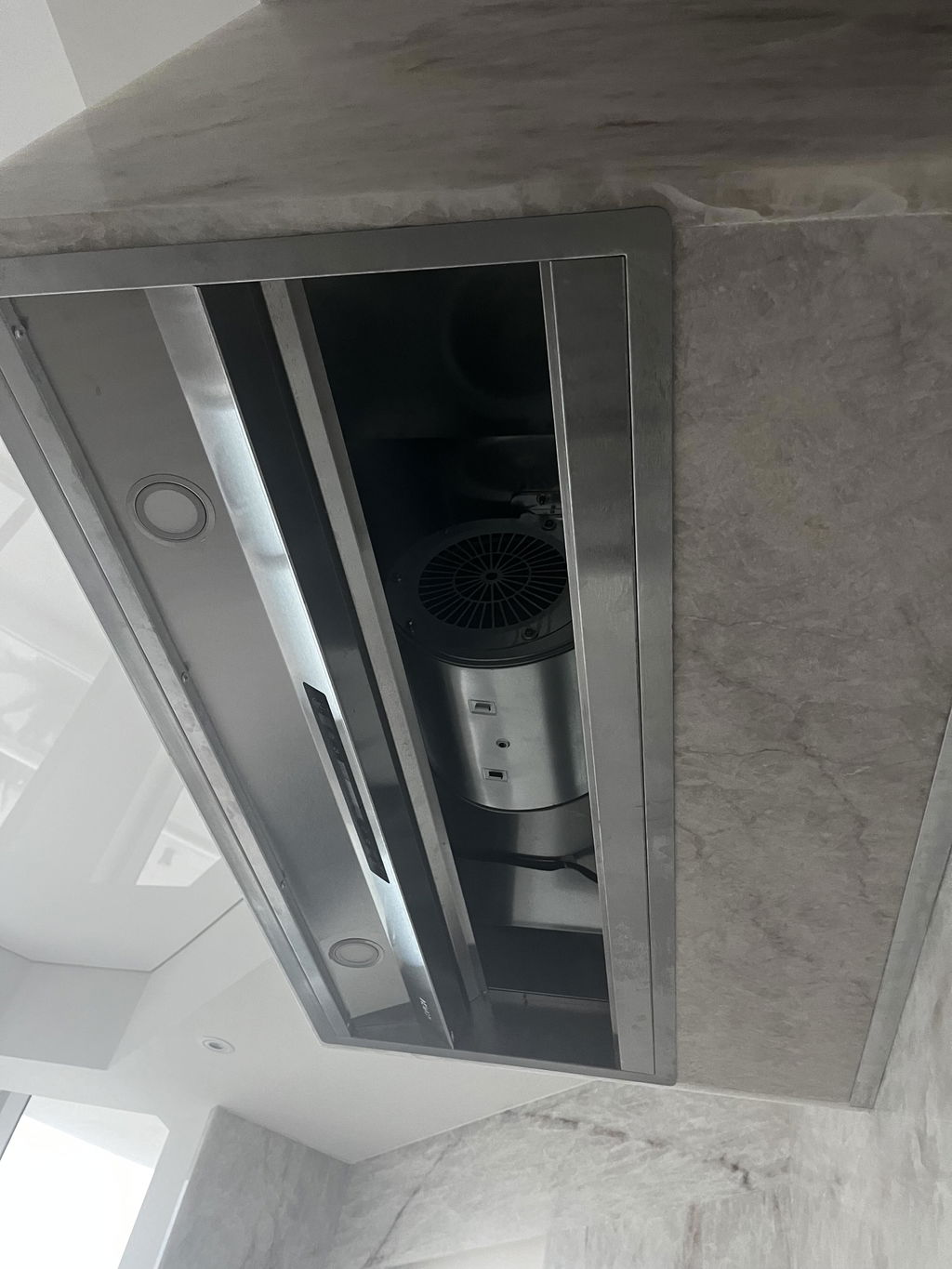
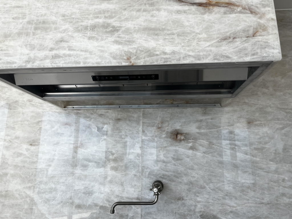
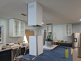
Please note, the image attached in this review is of the IKB02 model. Nevertheless, we greatly appreciate your review and look forward to continuing to provide you with top-notch products and service.
Thank you for your understanding and support!
Happy shopping!
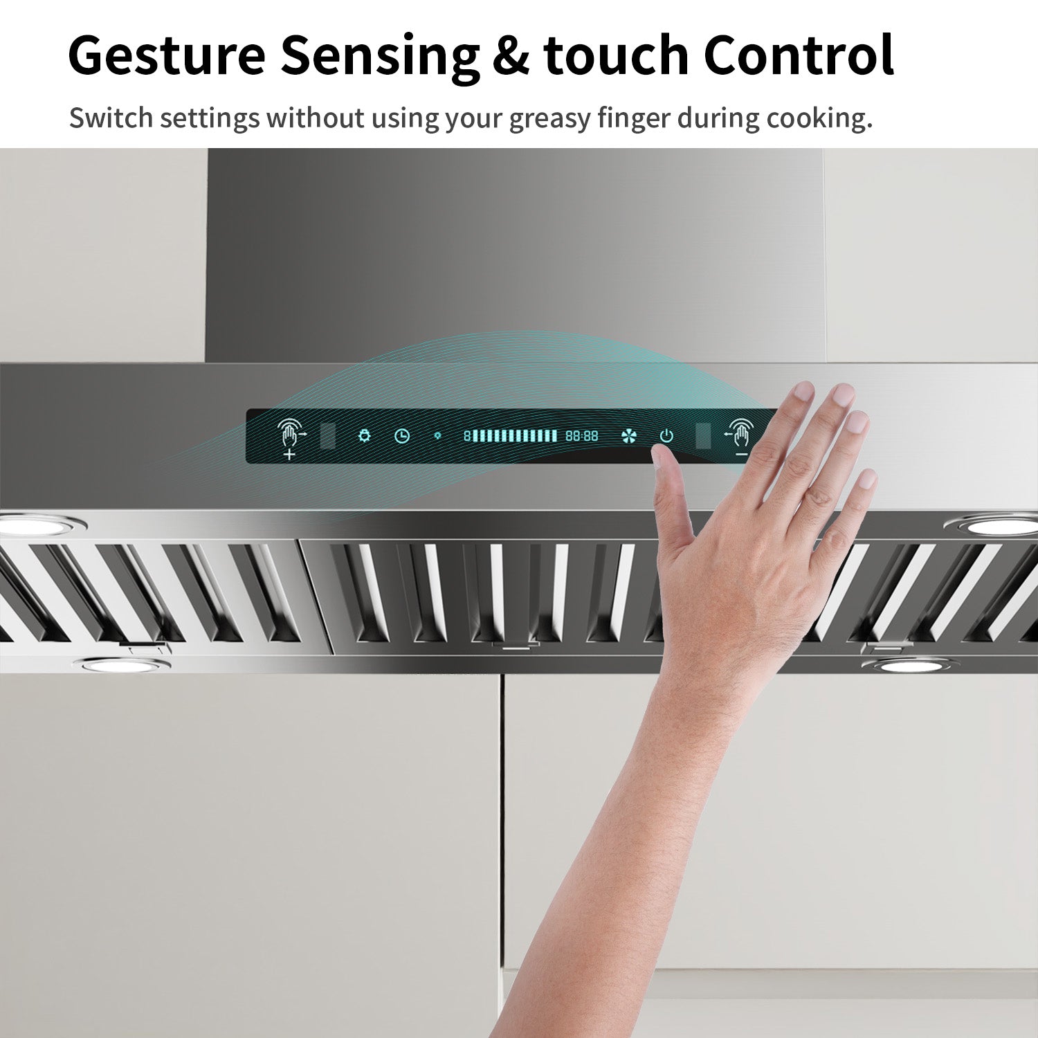
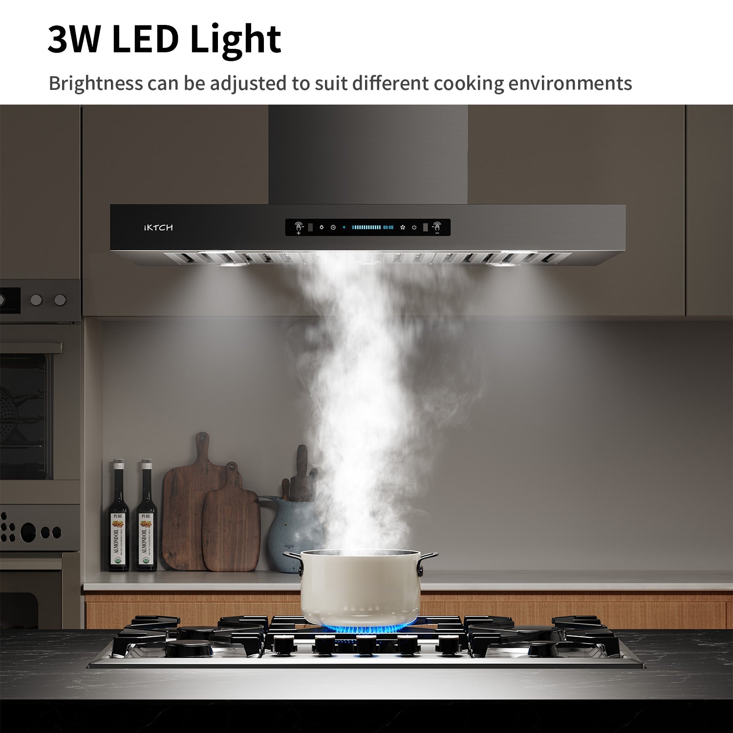
I love the hands free option.
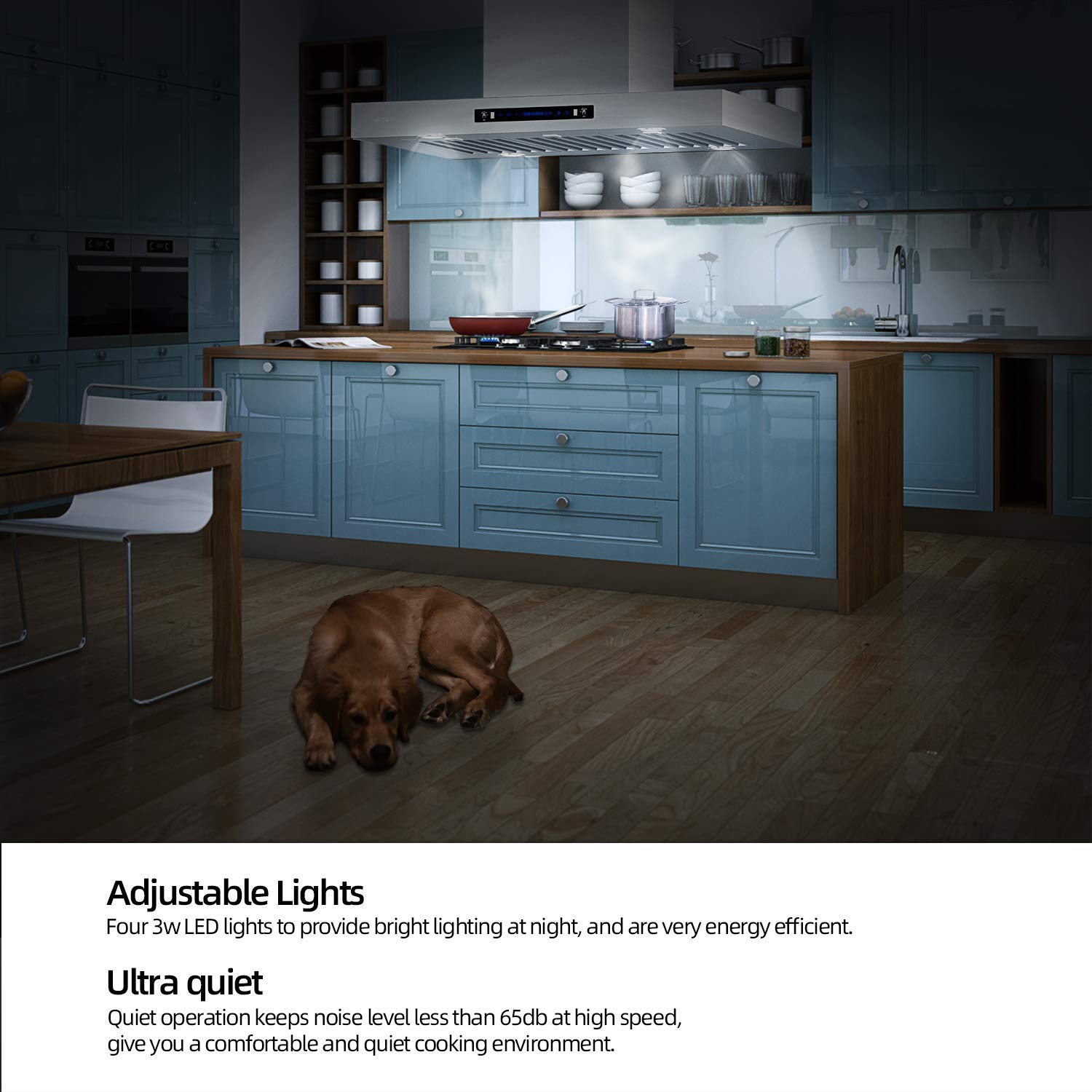
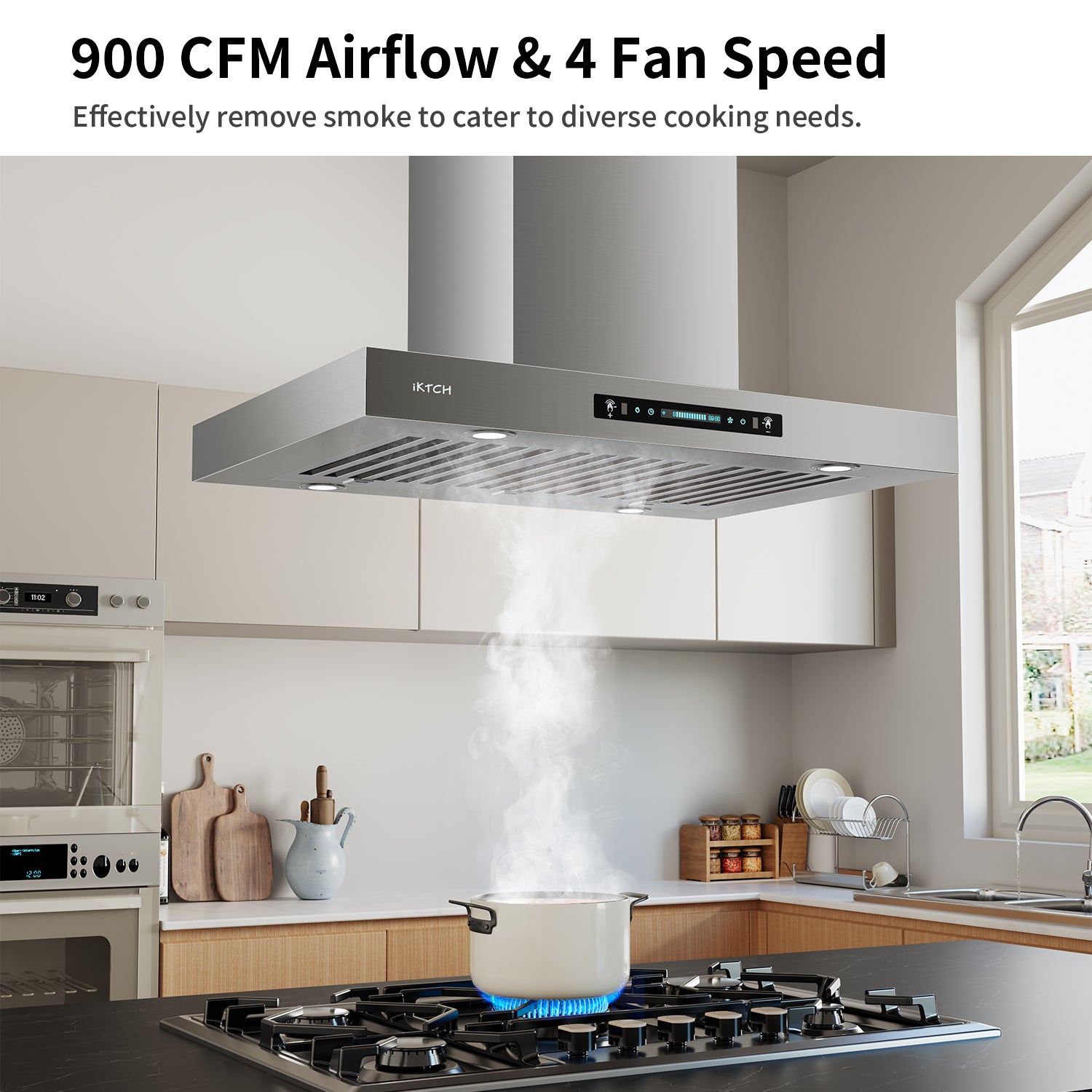
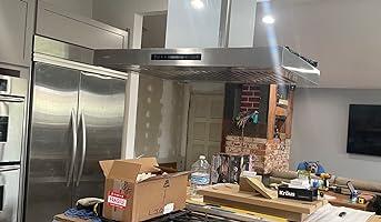
It is so powerful it actually blew some leaves off the deck outside. The noise level is OK.
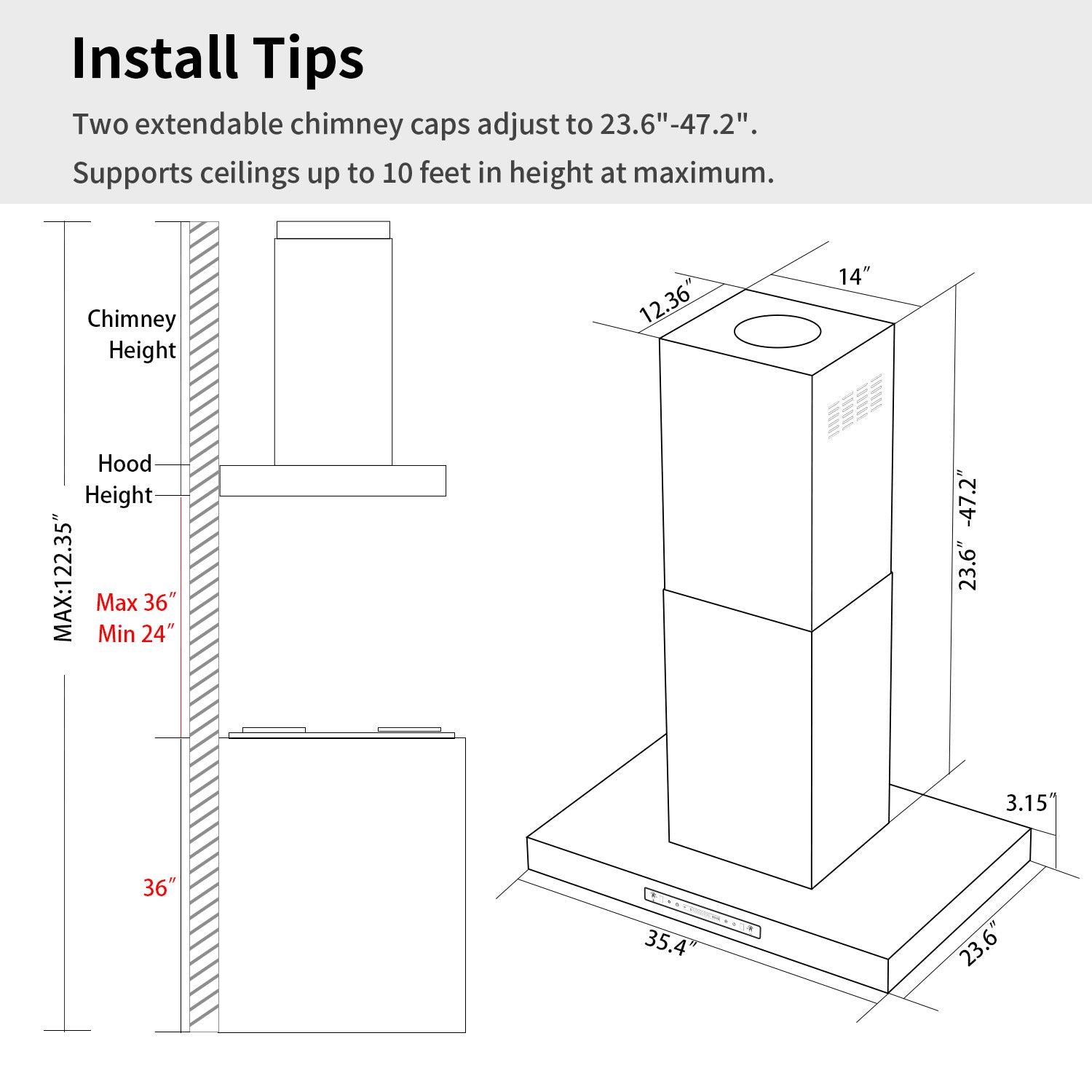
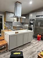
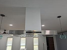
As others have noted, installing this hood under an 8' ceiling is a problem. I opted to use just one of the duct covers. First I drilled holes through the top plate and the supporting 2x4s in the attic to take 4 long bolts. Then I attached the flexible duct to the fan assembly. I attached the top plate to the "angle irons" and then to the fan & hood assembly on the counter top. I then slid the duct cover over from the top. Using the cardboard box it came in and bits of lumber I elevated the hood until the top plate was in position snug on the ceiling. Now the hard part: I crawled into the attic and working through the duct hole, jiggled the top plate around until I could slide the bolts from the bottom through the top plate and 2x4s, and then I installed washers and nuts. Tightening the nuts cinched the assembly nice and firmly to the ceiling.
I think I could have come up with a better design to make installation a lot less challenging. For one, everything is assembled with frustrating tiny little nuts and bolts. Bring your good glasses!
5/17/2024 update: I was contacted by Iktch and they generously resolved the issues I had to my satisfaction. Now that the hood is installed we are very pleased with the looks, performance, and the quality of the product. Updated 3 stars to 5 stars.

It suits my family in every way. Features, Price, simple installation.